In this extract will go from why we need to purifiers onboard ships and their basic principles. It will give us an in-depth understanding of the subject.
Need for purifiers?
Modern-day engines on ships are made to run with the poor quality of fuel so as to reduce costs. Thus to prevent unnecessary wear and tear of the engine and to maximize the efficiency this fuel should be purified. This is done by a purifier. The unwanted particles such as catfines, water and solids are removed in the purifier.
Principle
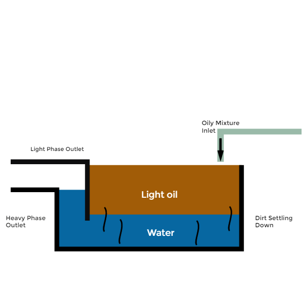
Consider a tank with a weir. When an oily mixture is introduced into the tank then due to the difference in density between the water and oil in the mixture the water will settle at the bottom and the oil will form a layer at the top. Any other heavy particles which may be present in the mixture will settle down into the bottom of the tank. The weir will act as a separation layer and allow the heavy liquid to be removed and we will be left with the light phase that is the oil.

The difference in density is the main criteria for separation.
In a purifier, we use centrifugal force instead of gravity to carry out the separation of the oil.
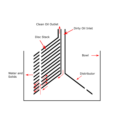
The centrifugal purifiers or separator consists of a bowl containing a set of discs stacked one on top of the other. The dirty oil flows down the distributor and up through the holes in the discs. The discs are given as they increase the surface area for separation.

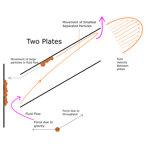
The principle of Separation between the angled plates

From the figure, it can be seen that any particle passing through the two discs is subjected to two forces one is the force due to gravity and the other is due to the flow of liquid. The velocity of the particle varies it being zero when in contact with the plate and maximum when it is between the two plates. The light particles pass through the centre and move towards the light fluid outlet while the heavy particles are acted upon by gravitational force due to there weight and move towards the disc and cling to it. These get accumulated at the edge of the plate and move out of the bowl once desludging takes place.
Interface
The concept of interface is rather easy to understand as opposed to the general idea of it being confusing. The separation line between the oil and water is known as the interface(e-line). To gain the fullest advantage from the disc stack the e-line should be located outside of it. On the other hand, if the e-line is located outside the water outlet baffle (top disc) discharge of oil in the water phase will take place.

As we can see from the figure, the interface denoted by the distance e from the centre should be maintained exactly at the holes in the discs. If it moves inside then chances of water entering into the oil side are more and vice versa. Normally we get different density bunkers at different ports and hence to maintain the e-line constant we have to either change the distance l or h. Normally “h” is changed by using various diameter gravity discs.
This brings us to the next new concept of gravity disc. But before that, we should know what are the factors which influence separation in a purifier
Factors influencing Separation in Purifier
- Feed inlet oil temperature
- Density of Oil
- RPM of the rotating bowl
- Back Pressure
- The throughput of the oil feed
Understanding the factors
- Feed inlet oil temperature: Before entering the purifier, the dirty oil passes through the heater. This increases the temperature, thus reducing the viscosity of the oil to be purified. The lower the viscosity, the better will be the purification.
- The density of Oil: As the dirty oil entering the purifier is heated to reduce the viscosity, the density also reduces. The lower the density, the better the separation.
- R.P.M of the rotating bowl: If the purifier has not achieved full RPM (revolutions per second), then the centrifugal force will not be sufficient enough to aid the separation.
- Back Pressure: The back pressure should be adjusted after the purifier is started. The backpressure varies as the temperature, density, viscosity of feed oil inlet varies. The backpressure ensures that the oil paring disc is immersed in the clean oil on the way of pumping to the clean oil tank.
- The throughput of oil feed: Throughput means the quantity of oil pumped into the purifier/hr. In order to optimize the purification, the throughput must be minimum.
Gravity Disc

It is very important to select the correct size of gravity disc to bring about proper purification of the oil. The gravity disc is responsible for locating the interface. Selection of gravity disc can be carried out by two methods
- Nomogram method
- Trial and error method
Nomogram method
Example 1
The specific gravity of treated oil at 15℃ is known.
Treating condition
- The specific gravity of treated oil: 0.925 at 15℃
- Treating temperature: 70℃
- Feed rate: 3000 L/h
Selection method
- Refer to the nomogram given in the figure above. Click on the figure to enlarge.
- From an intersection between falling curve ① of the specific gravity of 0.925 and the vertical line of 70℃, draw horizontal line ② to reach the vertical line of 100℃.
- Connect between the right end of line ② and the point of 3000 L/h on the treating capacity scale using straight-line ③.
- Read within which section of gravity disc inside diameter scale the intersection made by line ③ falls.
- For this [Example 1] select a gravity disc having an Inside diameter of φ79.
Example 2
The specific gravity of treated oil at a certain temperature is known.
Treating condition
- The specific gravity of treated oil: 0.944 at 50℃
- Treating temperature: 98℃
- Feed rate: 1250 L/h
Selection method
- Refer to the nomogram given in the figure above. Click on the figure to enlarge.
- From an intersection between rising curve ④ of the specific gravity of 0.944 and the vertical line of 50℃ (being converted to a specific gravity at 15℃), draw curve ⑤ along the falling curve to reach the vertical line of 98℃, then draw a horizontal line to reach the vertical line of 100℃.
- Connect between the right end of the horizontal line and the point of 1250 L/h on the treating capacity scale using straight-line ⑥.
- Read within which section of gravity disc inside diameter scale the intersection made by line ⑥ falls. For this [Example 2] select a gravity disc having an Inside diameter of φ71.5.
Reference:
SAMGONG -MITSUBISHI SELFJECTOR Operation Manual
Trial and error method
If a NOMOGRAM is not given then the trial and error method must be used. In this method, we start by using the gravity disc with the smallest inner diameter and then move towards the disc with a larger diameter. The advantage of this is that there is no chance of water entering into the oil side as we are starting with the gravity disc of lowest size though oil will go out from the waterside. For eg, if 63 mm diameter disc is showing an overflow of oil from the overflow port and 71.5mm does not show overflow then the right size of the disc would be 71.5 mm.
Conclusion
With this extract, we gain basic knowledge about the purifier. In further articles, I will post about the working and troubleshooting of the purifiers.
Let’s discuss more in comments down below
