Introduction
In the last post, we covered the basic principles of the purifier, now we head towards the working of purifiers. In this extract, we will go through the various operations that take place in a purifier. So without further delay, we will move towards the working of the purifier.
Prior to understanding the various operations we need to know about the parts of the purifying system.
Parts of Purifying System
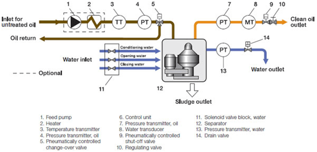
Gear Pump
The gear pump feeds feed oil to the purifier. It may be a separate unit or mounted on the horizontal shaft via a safety joint. It is selected to match a particular treating capacity.
Oil heater
The oil heater is installed between the gear pump and oil purifier. The oil heater warms feed oil fed by the gear pump to an optimum treating temperature. The heater is classified into steam and electrical types. The steam type is provided with a temperature control valve and the electrical type with a thermostat to control the temperature. Before oil is treated by the oil purifier, it must be heated up to a certain temperature according to the particular oil viscosity and nature.
3-way cylinder valve
The 3-way cylinder valve is a pneumatically operated valve which feeds feed oil to the purifier. When starting, stopped or discharging sludge, it changes to return the oil via the bypass piping to the tank.
Leakage Monitor Function (LM)
The Leakage Monitor detects leakage of treated oil from the bowl’s sludge outlet or heavy liquid output by means of a pressure sensor. It is located on the light liquid outlet. Hence when a leakage takes place it delivers an alarm signal to the automatic control panel.
Thus we have covered the important part of a purifier system and now we head towards the parts of the purifier.
Parts of Purifier
Drivetrain
It consists of the following parts:
Friction boss and friction pulley
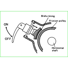
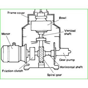
The friction boss is mounted on the motor. It is provided with slots in which the friction clutch are held together. This whole assembly is mounted inside the friction Pulley. This assembly is provided so that excess load on the motor does not arise due to heavyweight of the purifier. When the motor starts to rotate, due to the centrifugal force the friction clutch starts moving outside and come in contact with the friction pulley. Hence the friction pulley starts to rotate and therefore the purifier assembly rotates. A break is also provided on the friction pulley as to stop it in case of emergency.
Horizontal shaft
The motion is transmitted from the friction Pulley to the horizontal shaft. Bearings at either end of the shaft provide support. It is provided with a gear which meshes with the vertical shaft. Thus gives the necessary drive ratio to rotate the purifier at its rated 10000 RPM.
Vertical shaft
The whole purifier assembly is mounted on the vertical shaft. The vertical shaft and body are supported by upper springs and leaf springs. The function of the leaf springs is to reduce the vibrations. At the bottom of the vertical shaft, a thrust bearing is given so as to take the thrust load.
Water supplying device
The function of the water supplying device is to provide with bowl opening water and bowl closing water.
Operating water for bowl closing: to close the Bowl by moving up the main cylinder.
Operating water for Bowl opening: to open the bowl by lowering the main cylinder.
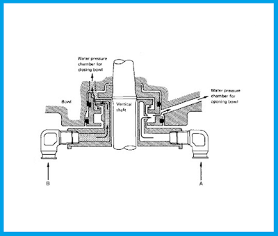
Solenoids provide the water to the supplying device. Bowl opening water is given for a small time on the other hand bowl closing water is given for a longer time. It is also given intermittently during the cycle. A pressure reducer is provided at the closing water solenoid. This water at reduced pressure is given.
Conditioning water
The conditioning water is provided two times during the cycle of operation of a purifier. Once prior to desludging to make the sludge soft. On the other hand, it is also provided desludging to fill the bowl with water. Thus when the feed starts oil will not exit through the heavy liquid outlet. It is provided through an inlet at top of the purifier assembly.
Bowl
The bowl is composed of bowl body, bowl hood and bowl nut which form a container. In the inside of the bowl, the separation chamber composed of discs and top disc, and distributor leading dirty oil from bowl inlet to separation chamber are incorporated. The further purifier has the main cylinder sliding up and down hydraulically in order to discharge solids separated and accumulated on the inside wall of the bowl during operation. Further, pilot valve assemblies to control the sliding of the main cylinder are provided at points on the periphery of the bowl body. Dirty oil led to separation chamber from dirty oil inlet through distributor passes through spaces between discs, with solids and water being separated midway, and thus becomes purified oil which is discharged outside continuously by centripetal pump[impeller(1)] on the upper part of bowl, while separated water is similarly discharged continuously by centripetal pump [impeller(2)].
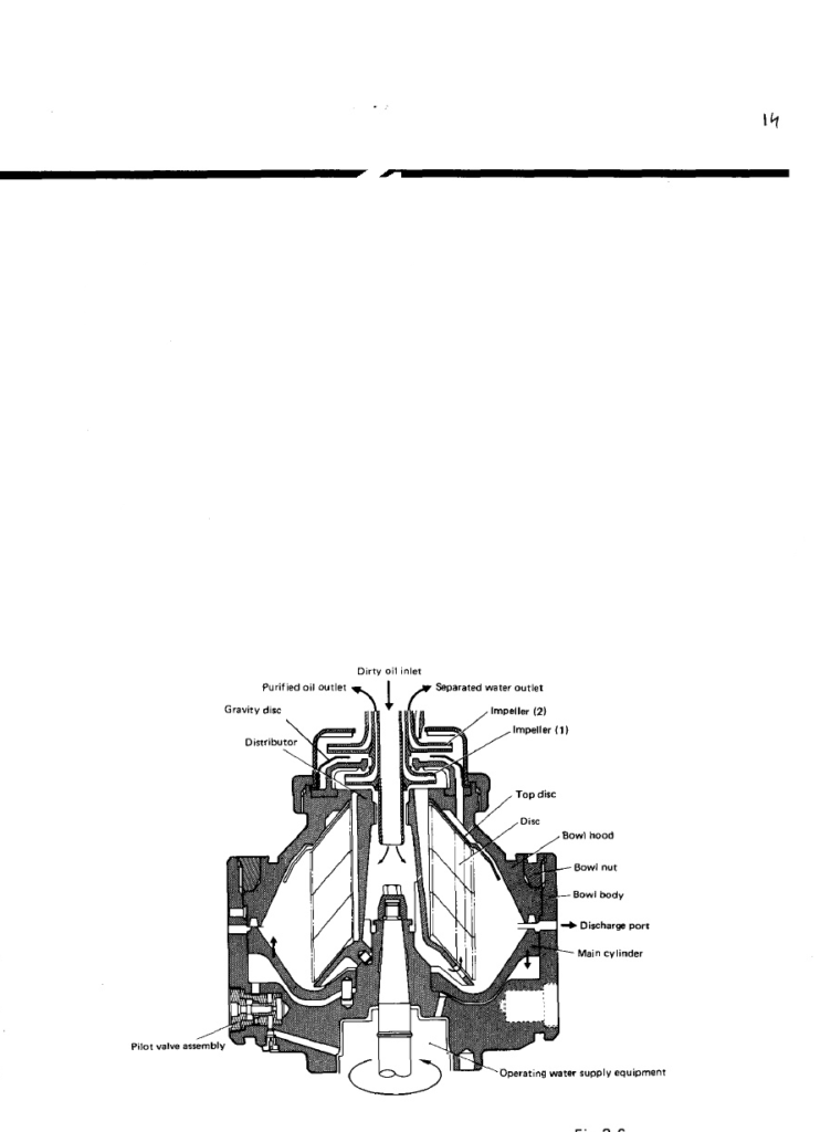
Processes in a Purifier
De sludging of Purifier
Sludge discharge is performed as follows.Centrifugal force acts on pilot valve, movingmit outwards and sealing the drain passage. The operating water gets filled in water pressure chamber for closing bowl. Under pressure of the operating water, main cylinder is pushed up to seal main seal ring for purifying operation. The operating water for closing bowl is constantly supplied to the water pressure chamber for closing bowl. Operating water within the water pressure chamber for closing bowl rotates with the bowl, and therefore pressure generated under centrifugal force and head pressure of operating water to be supplied are balanced to cause water level to be stable at a certain position.
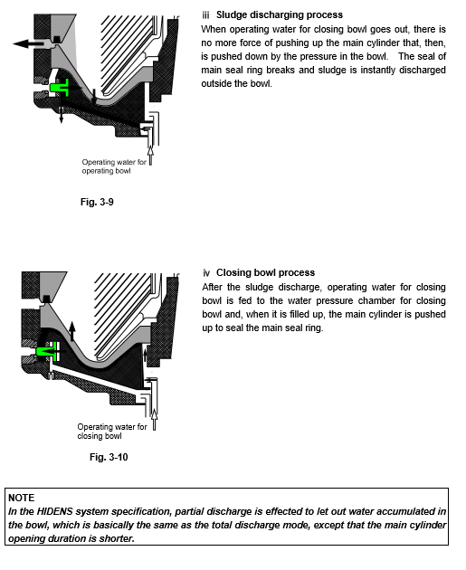
Operating water for the opening bowl is fed for a certain time to the water pressure chamber for the opening bowl. Part there of passes through, but remaining water is filled in the water pressure chamber for the opening bowl. Under pressure of the operating water, pilot valve slides in the counter radial direction. Seal in the packing part is broken and operating water for the closing bowl flows out of the bowl. With this, we have covered the working of the purifier. I will now cover the normally asked questions regarding purifiers.
Difference between a purifier and clarifier?
The basic difference between a purifier and a clarifier is that purifiers separate water and solid impurities from the oil. Whereas clarifiers separate only solid impurities from the oil. There is no gravity disc in a clarifier as there is no requirement of an interface. A purifier has a heavy liquid outlet, on the other hand, a clarifier does not have it. Any excess water which may be present is sensed by a water content sensor in the oil outlet and a desludging takes place emitting all water and separated solids. Thus in this way, a clarifier can be used as a purifier. The following table clearly explains the differences.
| Criteria | Purifier | Clarifier |
|---|---|---|
| Definition | Purifier is a type of centrifugal separator that we can use to separate two liquids with differnt densities | Clarifier is a type of centrifugal separator that we can use to separate solid impurifies from fuel |
| Separation | Fuel and water along with some solid particles | fuel and solid impurities along with some water |
| Process | A dam ring separates the fuel and water | A sealing ring separates the fuel from water and impurities |
| Requirement | Needs to be filled completely with water to generate the sealing ring | Does not need to be filled with water at all |
| Uses | For filtering lubricating oils | Cannot use for filtering lubricating oil unless the fuel is completely free of water. |
If the cat files in fuel are high then what should be done?
Cat fines are the particles which are present in the fuel and are highly erosive. Aluminium and silica are the commonly known cat fines. They are introduced in the processing stage of fuel. if URL contains a high amount of cat vines then it can lead to wear and tear of fuel pumps and other fuel injection equipment.
To prevent this purifier should be run in parallel. The best way to reduce cat vines is to have high purifier efficiency. the only way to maintain high purifier efficiency is by reducing the feet rate. Thus by running purifiers in parallel, it is possible to achieve minimum speed while taking into consideration the consumption.
Let’s discuss more in comments down below
